
Measurement is the foundation of quality control. You cannot improve what you cannot measure — and you cannot measure reliably without the right instrument. For many precision manufacturing environments, contact gauges have real limitations. They can deform soft materials. They cannot keep pace with high-speed production lines. They cannot reach inside complex geometries. And they introduce operator-dependent variation with every measurement.
Optical metrology solves these problems. It uses light instead of physical contact to measure dimensions, surfaces, and geometric features with extraordinary precision. In Six Sigma, optical metrology produces the measurement data on which the entire Measure phase depends. A measurement system that cannot reliably detect the variation it is supposed to find makes every downstream analysis unreliable.
Table of contents
Meaning of Optical Metrology
Optical metrology is the science of making precise measurements using light. It uses optical techniques to measure parameters including distance, displacement, surface topography, dimensions, and geometric tolerances — without physically contacting the part being measured. The origins of optical metrology trace to Thomas Young’s work on optical interference and the Michelson-Morley experiments in the 19th century.
Theodore Maiman’s invention of the laser in 1960 significantly advanced its capabilities by providing a coherent, high-intensity light source ideal for interference measurements. Today, optical metrology is used in aerospace, automotive, semiconductor, medical device, and precision engineering industries to verify parts against engineering specifications and feed Statistical Process Control systems.
Key Takeaways
- Optical metrology uses light to measure dimensional and surface parameters without physically contacting the part.
- Its origins trace to 19th-century work on optical interference by Thomas Young and the Michelson-Morley experiments. Theodore Maiman’s 1960 laser invention significantly advanced the field.
- A 2024 peer-reviewed review in PMC (National Institutes of Health) confirmed that optical metrology plays a central role in bridging macroscopic and nano-scale characterization in precision manufacturing.
- Key optical metrology techniques include interferometry, structured light profilometry, confocal microscopy, laser triangulation, and vision-based measurement systems.
- Optical metrology systems can achieve sub-nanometer resolution for surface characterization and enable 100% in-line inspection at production speed, according to Quality Magazine.
- In Six Sigma’s Measure phase, optical measurement systems must undergo Measurement System Analysis (MSA) and Gauge R&R validation before their data is used to build a process baseline.
- According to AIAG guidelines, a measurement system contributing more than 30% of tolerance variation is unacceptable for Six Sigma data collection purposes.

Public, Onsite, Virtual, and Online Six Sigma Certification Training!
- We are accredited by the IASSC.
- Live Public Training at 52 Sites.
- Live Virtual Training.
- Onsite Training (at your organization).
- Interactive Online (self-paced) training,
What Is Optical Metrology?
Optical metrology is the science of precise measurement using light. It covers a wide range of techniques that use light waves, laser beams, structured illumination, or imaging systems to measure dimensional and surface characteristics of physical objects.
AZoOptics defines it as “the science of making precise measurements using light, which has become indispensable across the aerospace, automotive, and electronics industries, where precision and quality control are crucial.”
Number Analytics offers a complementary definition: optical metrology is “a branch of metrology that deals with the measurement of optical properties and the characterization of optical components and systems. It involves the use of optical techniques to measure various parameters such as distance, displacement, surface topography, and optical properties like reflectance and transmittance.”
The defining characteristic is non-contact measurement. Light interacts with the part’s surface and returns information about its geometry, texture, and dimensions without a probe ever touching the material. This eliminates the deformation errors, wear effects, and access limitations that contact gauges produce.
A Brief History of Optical Metrology
The science of measuring with light is not a recent development. AZoOptics confirms that “the origins of optical metrology date back to pioneering work on optical interference by Thomas Young and the Michelson-Morley experiments in the 19th century, demonstrating its applicability for dimensional measurements.”
The pivotal development came in 1960. Theodore Maiman invented the laser — a source of coherent, high-intensity, single-wavelength light. AZoOptics confirms that this invention “unleashed optical metrology’s potential by providing an intense beam of highly coherent light ideal for interference measurements.”
In the decades that followed, advanced laser sources, high-resolution cameras, fast computing hardware, and sophisticated algorithms transformed optical metrology from a laboratory instrument into a production-floor tool. Today, optical metrology systems integrate directly into manufacturing lines, measure parts at production speed, and transmit data automatically to quality systems.
Key Optical Metrology Techniques
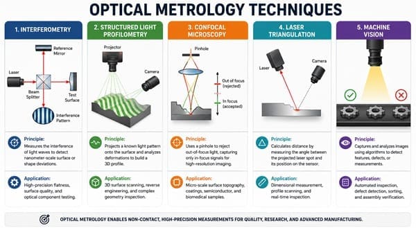
Several distinct techniques fall under the optical metrology umbrella. Each uses light differently and suits different measurement tasks.
Interferometry
Interferometry measures dimensions by analyzing the interference patterns produced when two beams of light combine. One beam reflects off a reference surface. The other reflects off the part being measured. Where the two beams combine, they produce interference fringes — patterns of light and dark bands that reveal surface variations at the nanometer scale.
Phase-Shifting Interferometry (PSI) and Coherence Scanning Interferometry (CSI) are two widely used variants. A 2024 AZoOptics review confirms both are used for “quality control in aerospace, automotive, and electronics industries, where precision and quality control are crucial.”
Interferometry achieves sub-nanometer resolution. It is the primary tool for measuring optical components, precision surfaces, and semiconductor wafers.
Structured Light Profilometry
Structured light profilometry projects a known pattern — typically a grid or series of fringes — onto the part’s surface. A camera captures how the pattern deforms as it conforms to the surface geometry. Software reconstructs a three-dimensional model of the surface from the deformation pattern.
A 2024 peer-reviewed review in PMC (National Institutes of Health) confirms that structured light profilometry provides “reliable evaluation across scales, from large structures to micro- and nano-scale features.” This range makes it one of the most versatile surface characterization techniques available.
Structured light systems can scan complex parts quickly. They suit aerospace components, automotive body panels, and large precision structures.
Confocal Microscopy
Confocal microscopy uses a focused spot of light that moves across the part’s surface point by point. The detector captures the reflected signal only from the focal plane, rejecting out-of-focus light. This selective detection produces high-resolution surface profile images with excellent depth discrimination.
The PMC 2024 review confirms confocal microscopy provides “reliable evaluation” for surface characterization. It suits micro-scale features, electronics components, and material texture analysis.
Laser Triangulation
Laser triangulation projects a laser spot or line onto the part’s surface. A sensor positioned at a known angle captures the reflected light. The position of the reflected spot on the sensor changes as the surface height changes. Software converts this position change into a dimensional measurement.
A peer-reviewed NIH study on inspection of parts manufactured by selective laser melting confirmed laser triangulation as one of five optical measurement systems evaluated for geometric dimensioning and tolerancing verification.
Laser triangulation suits continuous, in-line measurement at production speed. Displacement sensors, profile scanners, and 3D line scanners all use this principle.
Vision-Based Measurement (Machine Vision)
Vision-based measurement systems use cameras and image processing software to measure geometric features from 2D or 3D images. Features including hole diameters, edge positions, slot widths, and pattern registration are measured by analyzing the image directly.
Quality Magazine confirms that “vision-based metrology is a technology that can satisfy conditions for ideal gaging: a part can be placed in view, measurements of numerous features can be initiated simultaneously, and data can be saved and sent automatically.” It further confirms that vision systems can “enable 100% inspection” at high throughput rates.
Why Optical Metrology Outperforms Contact Gauges in Specific Situations
Contact gauging remains valid and widely used. But it has limitations that optical metrology specifically addresses.
Deformable materials. Contact probes apply force to the part’s surface. For soft metals, polymers, thin-walled parts, or coated surfaces, this force can deform the material or damage the coating. Optical measurement applies zero force.
Complex geometries. A contact probe must physically reach every feature being measured. Deep cavities, narrow slots, internal threads, and undercut features may be inaccessible to contact probes. Light can reach wherever it can reflect from.
Measurement speed. A contact probe measures one point at a time. An optical system captures thousands or millions of surface points simultaneously. For high-volume production environments, optical measurement supports 100% inspection at production line speeds.
Operator variation. Contact gauging introduces variation from probe placement, applied force, and part fixturing. Automated optical systems reduce this appraiser variation significantly. A peer-reviewed NIH study on surface roughness measurement confirmed that non-contact systems are preferable for in-line testing because they can “operate fast enough to cope with the production rate and robust enough for a reliable operation in a harsh environment.”
Fragile or contamination-sensitive parts. Semiconductor wafers, optical lenses, and medical implants cannot be contacted with measurement instruments without risking contamination or surface damage. Optical measurement keeps the part clean and undisturbed.
Also Read: Micromachining: What It Is, How It Works, and Why Quality Control Matters
Industries That Use Optical Metrology
Aerospace. Turbine blades, structural components, and optical instruments for space-based observation systems all depend on optical metrology. Tolerances are tight, geometries are complex, and the cost of an undetected defect is extreme. Number Analytics confirms aerospace as a primary optical metrology application, specifically for “testing and characterizing optical components used in telescopes and other space-based observation systems.”
Automotive. Body panels, powertrain components, and engine parts are measured at high volumes using structured light scanners and machine vision systems. Optical metrology confirms dimensional conformance at the production rate. The NIH peer-reviewed review confirms optical metrology’s role in automotive manufacturing.
Semiconductor. Semiconductor wafer inspection operates at dimensional scales where contact gauges are simply not viable. Interferometry, confocal microscopy, and vision systems verify circuit dimensions, wafer flatness, and surface defects at the nanometer scale. Number Analytics identifies semiconductor manufacturing as a key sector, specifically for “quality control and inspection of semiconductor wafers and components.”
Medical devices. Implants, surgical instruments, and diagnostic components require dimensional accuracy that must be documented for regulatory submission. The 2024 AZoOptics review confirms that “non-destructive 3D optical metrology techniques like digital holography enable quantitative measurement of biomaterials and micro-components under physiological conditions with sub-nanometer resolution.”
Additive manufacturing. Parts built by selective laser melting, binder jetting, and other additive processes have complex geometries and rough surfaces that challenge contact measurement. A NIH peer-reviewed study confirmed five distinct optical measurement systems for geometric dimensioning and tolerancing verification of additively manufactured parts.
Also Read: Microfluidics Manufacturing
Optical Metrology and Six Sigma: The Measurement System Connection
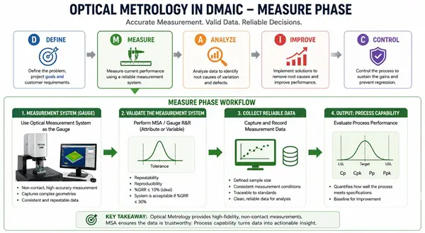
In Six Sigma’s DMAIC framework, the Measure phase produces the baseline data that drives every subsequent decision. That data is only as reliable as the measurement system that produces it.
Optical measurement systems used in Six Sigma projects must undergo Measurement System Analysis (MSA) — specifically Gauge R&R (Gauge Repeatability and Reproducibility) — before their data feeds a DMAIC project. Quality Magazine confirms that achieving Six Sigma standards requires careful attention to Gauge R&R. It identifies two specific sources of variability: the gauge itself and the operator who uses it.
The AIAG (Automotive Industry Action Group) guidelines, widely adopted in Six Sigma practice, define three acceptance zones:
- Below 10% of tolerance variation: Acceptable measurement system
- 10% to 30%: Marginal, use depends on application criticality
- Above 30%: Unacceptable, the measurement system must be improved
Optical measurement systems can offer specific Gauge R&R advantages over contact gauges. Quality Magazine confirms that automated optical systems can “confine a part’s location and facing” more consistently than manual contact gauging, and that “automated feeds can rapidly and consistently position parts to set inspection locations.” This automated consistency reduces appraiser variation — one of the two main components of Gauge R&R.
When an optical measurement system achieves a Gauge R&R below 10% of tolerance, its data is reliable for process capacapability analysis, control charting, and hypothesis testing throughout the DMAIC project.
Statistical Process Control (SPC) also benefits from optical metrology’s speed. Quality Magazine confirms that SPC “relies on sampling all or a subset of parts as they go through a process.” Optical systems that measure at production speed enable larger sample sizes, more frequent sampling intervals, and — where throughput allows — 100% inspection rather than statistical sampling.
Frequently Asked Questions: Optical Metrology
Q: What is optical metrology?
A: Optical metrology is the science of making precise measurements using light. It uses techniques including interferometry, structured light profilometry, confocal microscopy, laser triangulation, and machine vision to measure dimensional and surface parameters without physically contacting the part. It is used in aerospace, automotive, semiconductor, medical device, and precision engineering industries where high measurement precision and non-contact operation are required.
Q: What are the main techniques used in optical metrology?
A: The main optical metrology techniques are: interferometry (using light interference patterns to measure surfaces at nanometer resolution), structured light profilometry (projecting grid patterns onto surfaces to reconstruct 3D geometry), confocal microscopy (using focused light spots to build high-resolution surface profiles), laser triangulation (using reflected laser position to calculate distance and height), and machine vision (using cameras and image processing to measure geometric features from 2D or 3D images).
Q: Why is optical metrology better than contact measurement?
A: Optical metrology is not always better — but it offers specific advantages in specific situations. It applies zero force, so it does not deform soft materials or damage coatings. It can measure complex geometries that contact probes cannot physically access. It captures thousands or millions of surface points simultaneously, enabling 100% inspection at production speed. It reduces operator variation through automation.
These advantages make it the preferred measurement approach in semiconductor, medical device, additive manufacturing, and high-volume automotive applications.
Q: How does optical metrology connect to Six Sigma?
A: In Six Sigma’s DMAIC Measure phase, optical measurement systems produce the dimensional and surface data used to establish the process baseline. Before that data is collected, the optical measurement system must undergo Measurement System Analysis (MSA) — specifically Gauge R&R — to confirm it is producing reliable, repeatable results. According to AIAG guidelines used in Six Sigma practice, a measurement system contributing more than 30% of tolerance variation is unacceptable for data collection purposes.
Q: What industries use optical metrology?
A: Optical metrology is used in aerospace for turbine blades and space instrument testing, in automotive for body panel and powertrain component inspection, in semiconductor manufacturing for wafer and circuit inspection at nanometer scale, in medical devices for implant and instrument dimensional verification, and in additive manufacturing for geometric dimensioning and tolerancing verification of complex 3D-printed parts.
Q: What is the history of optical metrology?
A: Optical metrology’s origins trace to Thomas Young’s 19th-century work on optical interference and the Michelson-Morley experiments, which demonstrated light’s applicability for dimensional measurement. Theodore Maiman’s invention of the laser in 1960 significantly advanced the field by providing coherent, high-intensity light ideal for interferometry. In subsequent decades, advanced lasers, high-resolution cameras, and computing power transformed optical metrology from a laboratory instrument into a production-floor quality control tool.
Six Sigma Training for Measurement-Intensive Environments
Practitioners working in environments that use optical metrology need specific Six Sigma skills. They must design valid MSA studies for non-contact measurement systems. They must understand the unique fixturing and repeatability considerations that optical gauges present. They must be able to calculate Cpk from optical measurement data and interpret the result in the context of the part’s tolerance.
These are core Measure phase competencies at the Green Belt level and applied in depth at the Black Belt level.
At Six Sigma Development Solutions Inc., Measurement System Analysis, Gauge R&R, process capability, and DMAIC project management are covered in our Green Belt and Black Belt programs. Practitioners learn to validate the measurement systems they actually use — including non-contact optical systems.
We offer training in three formats:
- Onsite training — delivered at your facility, using your actual measurement systems in MSA exercises.
- Live virtual training — instructor-led sessions online covering the full Measure phase curriculum including optical and non-contact gauge considerations.
- Online training — self-paced Green Belt and Black Belt programs covering all IASSC-testable measurement system content.
Explore our Six Sigma training programs or contact our team to find the right program for your goals.
About Six Sigma Development Solutions, Inc.
Six Sigma Development Solutions, Inc. offers onsite, public, and virtual Lean Six Sigma certification training. We are an Accredited Training Organization by the IASSC (International Association of Six Sigma Certification). We offer Lean Six Sigma Green Belt, Black Belt, and Yellow Belt, as well as LEAN certifications.
Book a Call and Let us know how we can help meet your training needs.


