Table of Contents
What Is an Activity Network Diagram?
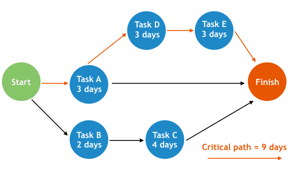
An Activity Network Diagram (AND), often referred to as an Activity Network Chart or Network Diagram, is a graphical representation of project tasks, illustrating the sequential connections between activities through the use of nodes and arrows. This visualization tool (network diagram) finds widespread application in project management, serving an indispensable role in pinpointing the critical path of a project (which is used to determine the expected time to complete the project).
An activity network diagram offers a visual depiction of the project’s activity sequence and interdependencies. It presents the initiation and culmination of each task, their respective time and resource demands, as well as the logical connections between them. By employing an activity network diagram, you gain the ability to conceptualize the project’s scope, timetable, and potential risks, ultimately aiding in the determination of the project’s critical path.
What is the Connection with Continuous Improvement (CI)?
ANDs are commonly used in project management to visualize and manage the sequence of tasks, dependencies, and the overall timeline for a project. However, they can also be applied in the context of Continuous Improvement (CI) initiatives to streamline processes, identify bottlenecks, and enhance overall efficiency. Here’s how ANDs can be used in Continuous Improvement:
- Process Mapping: ANDs can be used to map out the various activities and steps within a specific process. This allows for a clear understanding of the process flow, including inputs, outputs, and the sequence of tasks. Creating a visual representation of the process can make it easier to identify areas for improvement.
- Identifying Dependencies: In continuous improvement efforts, it’s crucial to understand how different activities or steps in a process are interconnected and dependent on each other. ANDs help in visualizing these dependencies, highlighting where one task must be completed before another can begin. Recognizing dependencies is essential for optimizing workflow and avoiding delays.
- Bottleneck Analysis: Continuous improvement often involves identifying bottlenecks or constraints that slow down the process. By using ANDs, you can pinpoint where these bottlenecks occur in the process and allocate resources and efforts to resolve them effectively.
- Streamlining Workflows: ANDs can be used to reconfigure or redesign processes for more efficiency. By analyzing the sequence of activities and dependencies, you can find opportunities to eliminate unnecessary steps, reduce wait times, and optimize the overall workflow.
- Resource Allocation: In a CI context, it’s important to allocate resources efficiently to ensure that activities are completed on time and within budget. ANDs can help in visualizing which tasks require more resources, allowing for better resource planning and allocation.
- Continuous Monitoring: Once improvements are implemented, ANDs can be updated to reflect the new process and ensure that the changes are sustained. Continuous monitoring using ANDs allows you to track progress, identify any emerging issues, and make further improvements as needed.
- Communication and Collaboration: Using ANDs to represent processes and improvement initiatives can facilitate better communication and collaboration among team members. It provides a common visual reference for discussing process changes and ensuring everyone is on the same page.
In summary, an Activity Network Diagram is a graphical representation of project tasks, illustrating the sequential connections between activities through the use of nodes and arrows. This visualization tool finds widespread application in project management, serving an indispensable role in pinpointing the critical path of a project. They provide a visual representation of processes, helping teams to understand, analyze, and optimize workflows. By using ANDs in a CI context, organizations can systematically identify and address inefficiencies, bottlenecks, and other issues that hinder productivity and quality, ultimately leading to more streamlined and effective operations.

Using an Activity Network Diagram to Identify Critical Paths
To identify critical paths using an Activity Network Diagram (AND), you need to follow a series of steps. Critical paths are the longest sequence of dependent tasks in a project, and they determine the minimum time required to complete the project. Here’s how to identify them:
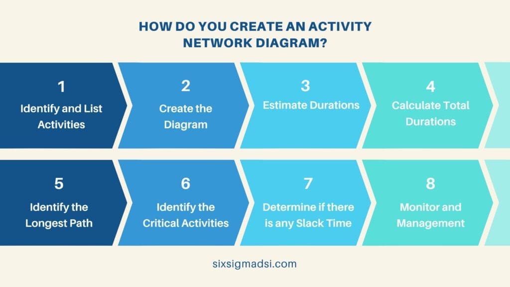
- Identify and List Activities: Begin by listing all the activities involved in your project. These activities should include their names, estimated durations, and any dependencies they have on other activities.
- Create the AND: Draw the AND using nodes (representing activities) and arrows (representing dependencies between activities). Each activity should be represented as a node, and arrows should indicate the direction of the dependencies (from the predecessor to the successor activity).
- Estimate Durations: Assign estimated durations to each activity on the AND. This helps determine how long each task is expected to take.
- Calculate Total Durations: With estimated durations in place, calculate the total duration for each path through the network. Start from the initial node and move through the network, adding up the durations for each path.
- Identify the Longest Path: The path with the longest total duration is the critical path. Any delay in activities on this path will directly impact the project’s overall timeline.
- Critical Activities: Within the critical path, identify the critical activities. These are the specific tasks that have zero slack or float, meaning they cannot be delayed without extending the project’s duration.
- Slack Analysis: Examine non-critical paths to identify activities with slack or float. Slack represents the amount of time an activity can be delayed without affecting the project’s overall duration. Non-critical activities can be delayed by the amount of slack they have.
- Monitoring and Management: Focus your attention on the critical activities and monitor them closely. Any delays in these critical tasks will cause project delays. Additionally, keep an eye on non-critical activities with little slack, as they might become critical if there are unexpected delays.
By following these steps, you can effectively use an Activity Network Diagram to identify critical paths in a project. Critical path analysis is a fundamental tool in project management to ensure that the project stays on schedule and to manage potential risks and delays.

Here’s an Example
Let’s say you are managing a quality improvement project for a manufacturing company that produces smartphones. The goal is to enhance the quality of the product by implementing various quality control measures. Your project plan includes several activities:
- Research and analysis of quality standards.
- Supplier selection and quality assurance agreements.
- Employee training on quality control procedures.
- Implementation of new quality testing equipment.
- Quality inspection during the production process.
- Final product testing and quality assurance.
To identify the critical path for quality planning, you would create an AND that maps out these activities, along with their dependencies and durations. The critical path is the longest path through the network, meaning it represents the sequence of activities that will take the most time to complete. In quality planning, you would typically consider the critical path to determine where any potential delays could impact product quality.
For our example:
- Activity 1 (Research and analysis of quality standards) takes 2 weeks.
- Activity 2 (Supplier selection and quality assurance agreements) takes 3 weeks.
- Activity 3 (Employee training) takes 4 weeks.
- Activity 4 (Implementing new quality testing equipment) takes 5 weeks.
- Activity 5 (Quality inspection) takes 3 weeks.
- Activity 6 (Final product testing) takes 2 weeks.
In this case, the critical path is as follows: Activity 1 (2 weeks) -> Activity 2 (3 weeks) -> Activity 4 (5 weeks) -> Activity 5 (3 weeks) -> Activity 6 (2 weeks), which totals 15 weeks.
This means that if any of the activities on this critical path is delayed, it will result in a delay in the overall project completion, potentially affecting product quality. Therefore, in quality planning, you would closely monitor and manage these critical activities to ensure that the project stays on track and maintains the desired product quality standards.
Have you ever used a network diagram in project management? We’d love to hear from you!
Feel free to leave your thoughts, experiences, or inquiries in the comments section below.


