Computer-Aided Design (CAD) is the use of computer systems to assist in the creation, modification, analysis, or optimization of a design. CAD is commonly used in various industries, including architecture, engineering, product design, and manufacturing. It allows for more precise drawings and models, leading to better productivity, efficiency, and communication.
Table of contents
What is Computer-Aided Design?
Computer-Aided Design (CAD) refers to the use of computer systems (or workstations) to aid in the creation, modification, analysis, or optimization of a design. The designer uses CAD software to increase productivity, improve design quality, enhance communication through documentation, and create a database for manufacturing.
It serves as an automation tool for the design process, allowing designers to visualize and improve designs, simulate real-world behavior, and document the design effectively.
CAD helps designers by providing tools that automate time-consuming tasks, improve accuracy, and facilitate the analysis of designs. Over the years, it has become an integral part of various industries such as manufacturing, engineering, architecture, and construction.
The system enables the creation of both two-dimensional (2D) and three-dimensional (3D) models, making it a valuable asset in product design and development.
Here’s a breakdown of what CAD encompasses:
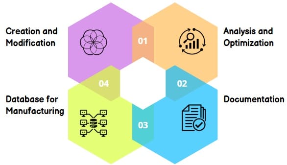
- Creation and Modification: CAD allows designers to create 2D and 3D models of products, parts, and assemblies. It facilitates easy modification and iteration of designs, saving time and resources.
- Analysis and Optimization: CAD software often integrates with analysis tools (e.g., Finite Element Analysis – FEA) to simulate and analyze design performance. This allows designers to optimize designs for factors like strength, stress, and fluid flow.
- Documentation: CAD systems generate precise technical drawings and documentation for manufacturing. This improves communication and reduces errors in the production process.
- Database for Manufacturing: You can use CAD models to generate data for Computer-Aided Manufacturing (CAM) systems. This seamless integration streamlines the transition from design to production.
Key Features of CAD
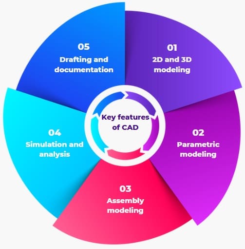
- 2D and 3D modeling: Creation of both 2-dimensional and 3-dimensional representations of objects.
- Parametric modeling: The ability to change dimensions and have the model automatically update.
- Assembly modeling: The ability to combine multiple parts into a complete assembly.
- Simulation and analysis: Integration with tools to analyze design performance.
- Drafting and documentation: Generation of technical drawings and documentation.
Definition of CAD Tools
CAD tools blend three essential sets: geometric modeling, computer graphics, and design tools. Geometric modeling involves creating digital representations of objects. Computer graphics provide visual feedback of these models. Design tools, including analysis codes and optimization methods, help refine these models into practical designs.
The goal of CAD tools is to offer fast and reliable solutions, helping designers quickly test multiple alternatives. CAD tools can range from simple geometric manipulations to advanced analysis and optimization tools, like finite element modeling.
Why Implement a CAD System?
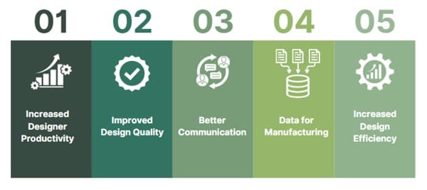
Implementing CAD in an engineering design process offers several key benefits:
- Increased Designer Productivity: CAD helps designers visualize products and components more quickly, reducing time spent on creating designs.
- Improved Design Quality: CAD allows for detailed engineering analysis, reducing errors and improving design accuracy.
- Better Communication: CAD ensures clearer drawings, better documentation, and reduced errors, improving communication between teams.
- Data for Manufacturing: CAD helps generate data for manufacturing, linking the design phase with production.
- Increased Design Efficiency: CAD minimizes waste and optimizes the design process, leading to cost and time savings.
Functional Areas of CAD
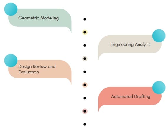
CAD systems typically perform a range of tasks grouped into four functional areas:
- Geometric Modeling
- Engineering Analysis
- Design Review and Evaluation
- Automated Drafting
Geometric Modeling is the process of creating the geometric representation of an object using mathematical models. The graphics terminal displays and manipulates these models, allowing the designer to interact with and modify the design. The system can generate 2D and 3D models and allow operations like scaling, rotation, and other transformations.
Engineering Analysis involves using the system to perform various types of analysis, such as stress-strain calculations or heat transfer computations. The CAD system can also calculate mass properties of the object, including surface area, volume, weight, center of gravity, and moment of inertia.
Design Review and Evaluation is an essential part of CAD. It involves checking the accuracy of designs, ensuring that they meet specifications. Designers can zoom in on details, check for interference between parts, and use animation to visualize the motion of mechanisms. This ensures the design’s feasibility before moving to manufacturing.
Automated Drafting is the process of automatically generating engineering drawings from the CAD model. This includes automatic dimensioning, generating cross-hatched areas, and producing sectional and enlarged views of the model. CAD systems can significantly speed up the drafting process, increasing productivity and accuracy compared to manual drafting.
Key Hardware Components in a CAD System
A modern CAD system relies on interactive computer graphics (ICG) and involves several hardware components:
- Digital Computer (CPU) – This is the central processing unit of the system, which processes information and stores data.
- Secondary Storage – It stores files related to engineering drawings, programs, and CAD software. This includes magnetic tapes and discs.
- Design Workstation – The visible part of the CAD system, it interfaces with the CPU, generates graphic images, and translates computer commands into operating functions.
- Graphics Terminal – This screen displays the designs.
- Operator Input Devices – These devices allow the user to interact with the system. They include:
- Cursor Control Devices – Thumb wheels, joysticks, light pens, and electronic tablets.
- Digitizers – Convert physical drawings into digital data.
- Alphanumeric Keyboards – Used for entering commands and data.
The Output Devices include plotters, printers, and computer-output-to-microfilm (COM) units, which help produce hard copies of designs and drawings.
CAD Workstation Classification
CAD systems can be classified based on their hardware configurations:
- Mainframe-Based Systems – These are large-scale systems typically used by large organizations.
- Minicomputer-Based Systems – Mid-sized systems suitable for small to medium-sized enterprises.
- Microcomputer-Based Systems – Personal computer systems suitable for small design tasks.
- Workstation-Based Systems – High-performance systems used for complex design tasks.
Each configuration offers different levels of processing power and capabilities, suitable for different scales of design tasks.
CAD Software
CAD software is a collection of programs designed to facilitate interaction with the computer graphics system. The software helps generate images, manipulate them, and execute various functions required for CAD work.
Apart from graphics-related tasks, CAD software may include specialized programs for functions like design analysis (e.g., finite element analysis) and manufacturing planning.
Features of CAD Software
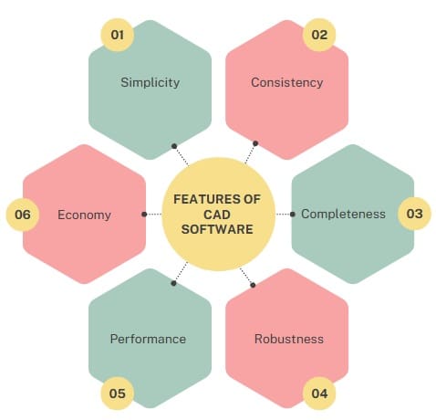
- Simplicity – The software should be easy to use.
- Consistency – The system should operate predictably, enhancing user experience.
- Completeness – The software should include all necessary functions without omissions.
- Robustness – The system should be able to handle minor user errors without crashing.
- Performance – The software should be efficient, responding quickly and reliably.
- Economy – The software should not be prohibitively expensive.
Types of CAD Software
- 2D CAD – It uses basic geometric shapes to create flat drawings. Examples include AutoCAD and CATIA.
- 2.5D CAD – A transition between 2D and 3D CAD, focusing on prismatic models that represent depth.
- 3D CAD – It allows designers to create realistic 3D models that they can view and rotate from any angle. Examples include Autodesk Inventor, SolidWorks, and CATIA.
Further classification of 3D CAD
- Wireframe Models – These models represent the object’s skeleton using lines and arcs. They are not commonly used anymore.
- Surface Models – These models are created by joining 3D surfaces, resulting in realistic objects.
- Solid Models – The most advanced type of model, solid models represent objects with properties such as weight, volume, and density.
Functions of CAD Software
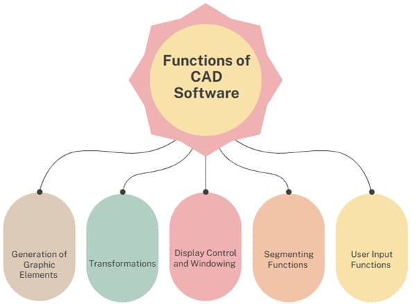
CAD software includes several important functions, such as:
- Generation of Graphic Elements – The software helps generate basic shapes and objects.
- Transformations – It allows the modification of shapes, such as scaling, rotating, and translating objects.
- Display Control and Windowing – The software offers tools to control how the objects are displayed on the screen.
- Segmenting Functions – This includes breaking down complex designs into manageable parts.
- User Input Functions – Tools for interacting with the design, such as input devices and command interfaces.
Traditional vs. CAD Design Process
The conventional design process typically includes the following steps:
- Recognition of Need: The first step is identifying the need for a design.
- Problem Definition: Designers must define the part’s shape, size, materials, and operating conditions.
- Synthesis of Design: The designer creates preliminary sketches, outlining the part’s dimensions, material properties, and loading conditions.
- Analysis and Optimization: The design is analyzed to ensure it meets safety standards and optimized for size, material efficiency, and cost.
- Evaluation: The design is evaluated to check if it satisfies all problem specifications.
- Presentation: The final design, with necessary drawings, is presented.
Advantages of CAD over Conventional Design
CAD greatly enhances design efficiency compared to conventional methods, particularly in geometric modeling, engineering analysis, and drafting.
Geometric Modeling: CAD allows precise mathematical descriptions of an object’s geometry. Early systems used wireframe models, while modern systems use 3D solid modeling.
Engineering Analysis: CAD can perform various analyses, including stress, strain, and heat transfer calculations. Advanced CAD systems use the finite element method (FEM) for detailed simulations.
Design Review & Analysis: CAD provides tools for interference checking (ensuring that parts fit together correctly) and kinematic analysis (simulating motion in mechanisms).
Automated Drafting: CAD automates tasks like dimensioning, scaling, and creating sectional views, improving drafting efficiency.
Benefits of CAD
- Improved Engineering Productivity: CAD streamlines the design process, allowing faster creation of accurate designs.
- Reduced Manpower Needs: With automation, fewer personnel are needed for manual tasks.
- More Efficient Operations: CAD eliminates errors and streamlines production, reducing overall time and costs.
- Easy Customization: CAD systems make it easier to modify designs based on customer requirements.
- Lower Waste and Cost: CAD helps reduce material waste and machining time through optimization.
- Improved Accuracy: CAD ensures precision, reducing the chances of design errors.
- Better Designs: The iterative nature of CAD allows designers to explore multiple alternatives, leading to better designs.
Limitations of CAD
Despite its benefits, CAD comes with some challenges:
- Large System Requirements: CAD systems require significant memory and processing power.
- Expensive Software and Hardware: The initial investment for CAD systems, including both software and hardware, can be high.
- Skilled Personnel Needed: Skilled professionals are required to operate and make the most of CAD systems.
- Learning Curve: CAD systems can be complex and time-consuming to learn, especially for users new to the software.
Evaluation Criteria for CAD/CAM Systems
When selecting a CAD/CAM system, various criteria should be considered:
- Cost: The total cost of implementation, including software and hardware.
- Compatibility: The system should be compatible with existing in-house systems and tools.
- Technical Specifications: The system should meet technical requirements, such as processing speed, memory, and graphical capabilities.
- User Experience: The system should be user-friendly and adaptable to the needs of the design team.
- Vendor Credibility: The reputation and support services provided by the CAD/CAM system vendor are critical factors.
- Performance Benchmarks: The system should be tested against specific performance benchmarks to ensure it meets the organization’s needs.
Role of CAD in Engineering Practice
In engineering, CAD is utilized in multiple ways:
Drawing and Documenting Designs: CAD helps create detailed, accurate designs and documentation.
Visual Tools: CAD allows for the generation of shaded images and animated displays, giving designers a clearer view of the product.
Engineering Analysis: CAD can perform complex engineering analyses on geometric models, such as finite element analysis (FEA).
Process Planning: CAD is used to generate NC (Numerical Control) part programs and plan processes.
The full potential of CAD in an engineering environment requires a study of a product cycle. This cycle involves various stages like concept design, detailed design, analysis, and production.
Final Words
Computer-Aided Design (CAD) revolutionizes the engineering and design process. By allowing more precise modeling, faster iterations, and in-depth analysis, CAD has made design work more efficient and accurate. The CAD system benefits organizations by improving productivity, reducing costs, and enhancing design quality.
However, the implementation of CAD comes with challenges, such as high costs and the need for skilled personnel. Despite these challenges, CAD systems are crucial for modern engineering, providing an essential tool for designers, engineers, and manufacturers.

About Six Sigma Development Solutions, Inc.
Six Sigma Development Solutions, Inc. offers onsite, public, and virtual Lean Six Sigma certification training. We are an Accredited Training Organization by the IASSC (International Association of Six Sigma Certification). We offer Lean Six Sigma Green Belt, Black Belt, and Yellow Belt, as well as LEAN certifications.
Book a Call and Let us know how we can help meet your training needs.

